Contents
Introduction
An OFDM audio modem that uses speaker as transmitter and microphone as receiver is developed. Communication standards are established during the development since the audio modem is required to be inter-operable between different groups. Additionally, error correcting code is implemented to help improve the robustness of the system to noise. The system could achieve about 10Kbit/s with zero error rate with a setup using average speaker and microphone.
Overall System Design
OFDM design
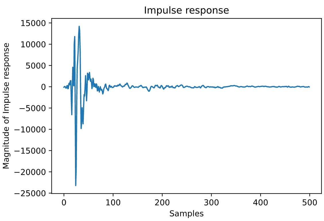
The overall idea of OFDM is to split a limited bandwidth chanel into a number of subcarriers. Each subcarrier carries a constellation symbol that is modulated with 4-QPSK with Gray coding. The 0 frequency dc subcarrier bins are not used and the upper half frequency bins are placed with complex conjugate of reversed sequence of the symbols placed in the lower half frequency bins. Therefore, real signal can be obtained in time domain after taking the IFFT. Additionally, cyclic prefix is added to the beginning of the OFDM block by repeating the last several symbols of the OFDM block. Cyclic prefix acts as a guard interval to overcome the intersymbol interference introduced by the overlapping of previous symbols. The length of the cyclic prefix should be at least the length of the channel response. The DFT length and the cyclic prefix length should be chosen accordingly to make sure the cyclic prefix does not waste too much of the data rate. In this experiments, a cyclic prefix of 256 is chosen as most of the tested channels have a length of around 200 samples as shown in figure below. The number of subcarriers is chosen to be 2048 which is a compromise between using more computational power and better robustness. A sampling frequency of 44100 is chosen.
Overall transmitting signal
As shown in the figure below, the transmitting signal consists of an initial chirp for synchronization and followed by a filler frame before the random known OFDM symbols for channel estimation. The OFDM filler block is inserted as one group uses modified Schmidl and Cox method for synchronisation and their method works only if there is some gap between the chirp signal and the known OFDM symbols. After the known OFDM symbols, the data payload OFDM symbols are transmitted. Finally, an inverse chirp is transmitted for symmetry and it can also be used to measure the actual sampling frequency of the devices providing the information of the decoded file length.
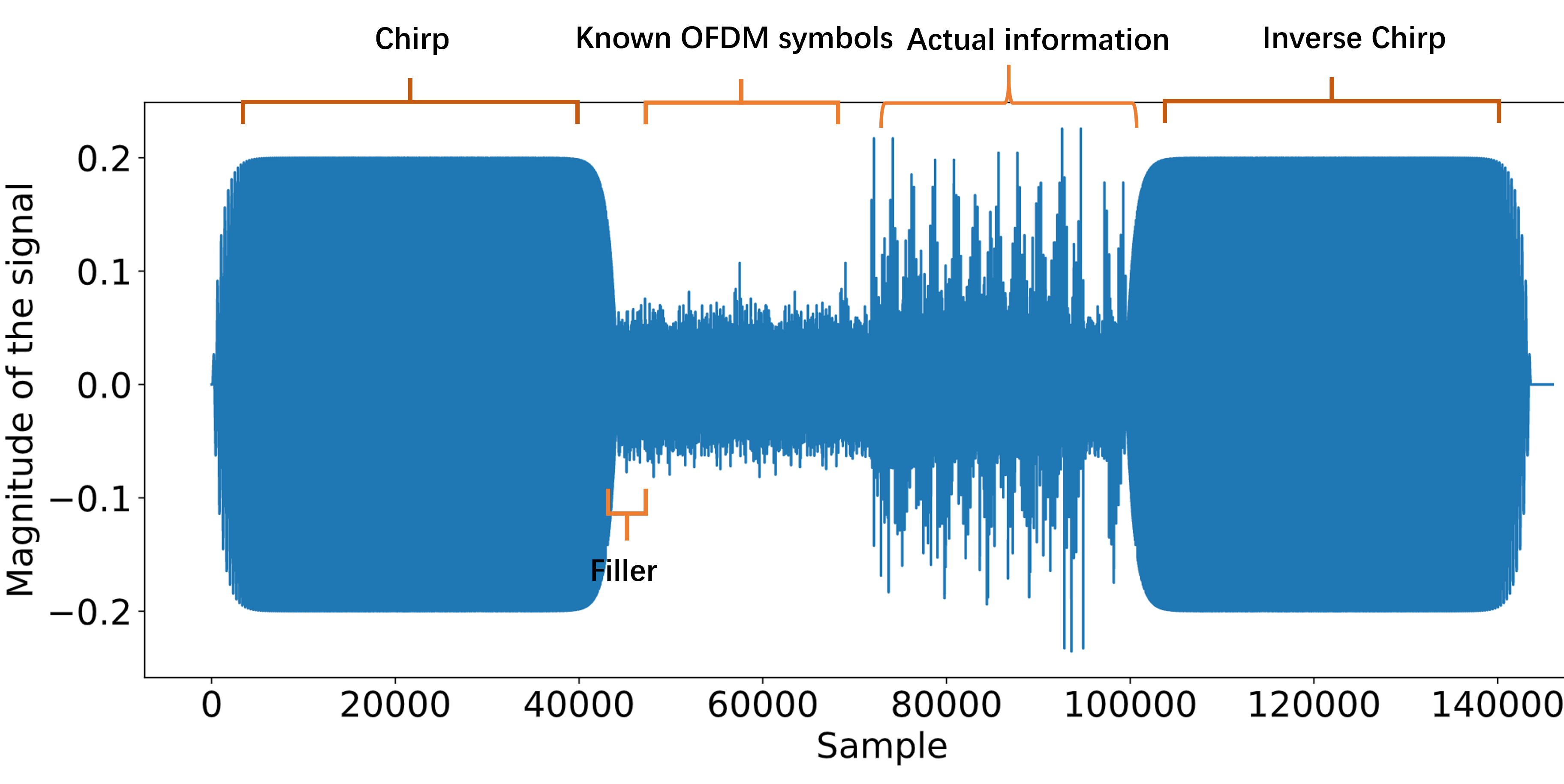
For the data payload, a random OFDM preamble block is added each 10 OFDM data blocks for some groups to do channel re-estimation and phase adjustments and can be ignored if some groups are not using them.
Frequency bins selection
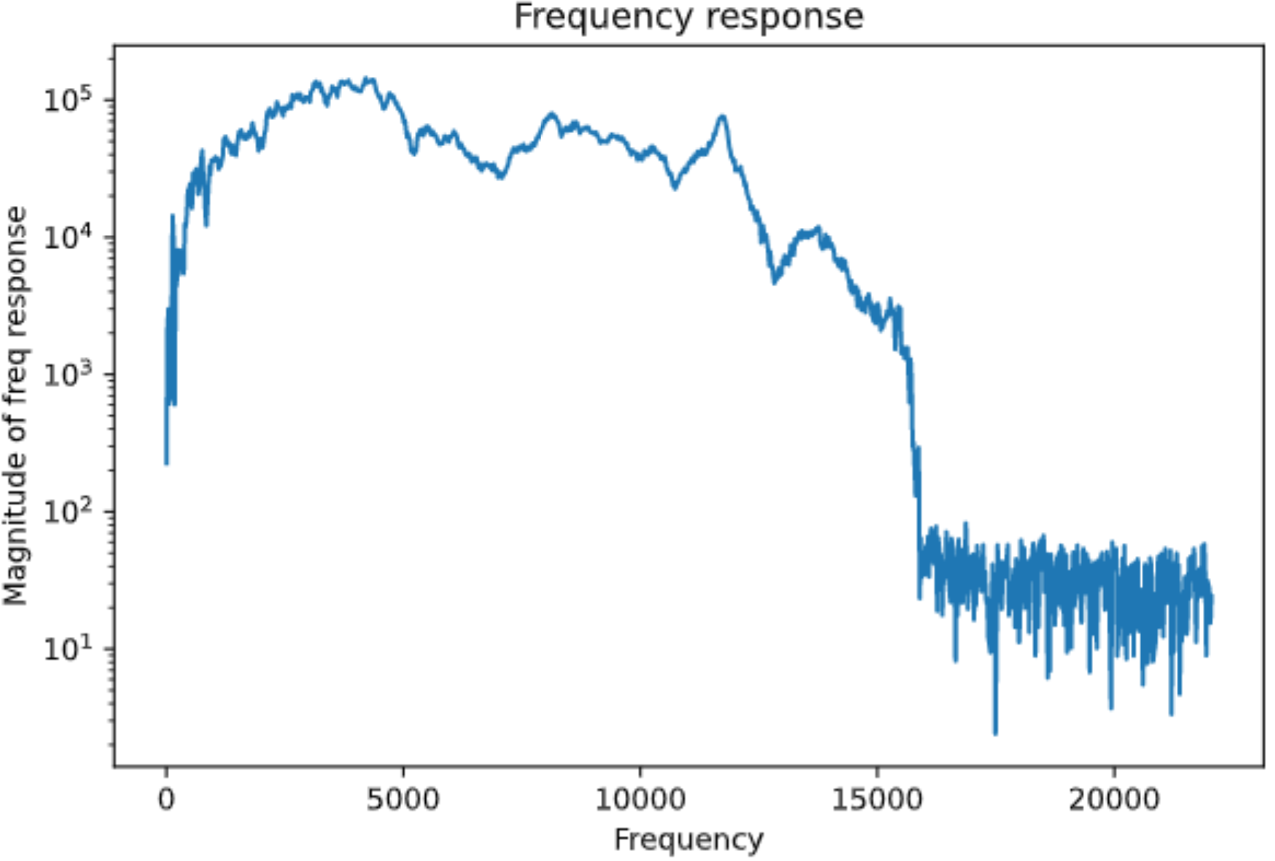
The frequency response figure shows that the channel response for lower frequency ( < 100 Hz) and higher frequency ( >15000Hz) are much worse then the middle range frequency by order of magnitudes. Therefore, only a selective range of frequency bins are used for the data OFDM blocks. A comparison between different frequency bins that is used for the data OFDM symbols is drawn in table below (require). The choice of 40-575 bins was inferred directly from the channel frequency response figure and it was proven to be the best choice for my channel from . However, this is based on our setup and the results could varies for different setups and a range of 50 to 700 frequency bins is chosen in the standard to make sure similar performance can be achieved on different channels. The unused bins are randomly padded rather than zero padded to avoid spikes in time domain.
Starting frequency: 50/1024∗(44100/2)=1077Hz
Terminating frequency: 700/1024∗(44100/2)=15073Hz
Channel estimation
Channel measurement is done by using pseudo-random known OFDM symbols. Let X be the vector of the known OFDM symbols, Y be the vector of the received OFDM symbols, H be the vector of the discrete Fourier transform of the channel impulse response i.e., frequency response. Since the channel acts as a convolution of the transmitted signal in time domain, and the circular convolution in time domain is equivalent to the element-wise product in dft domain: Y=H⋅X→H=Y/X
The OFDM symbols are repeated to reduce the channel estimation error which is induced by the random noise of the channel. Table below(Requires) shows the comparison between different number of repetition of the known OFDM symbols when no error correction coding and pilot symbols for phase adjustments are applied to keep the results make sure the comparison is fair. The results show that 20 should be the best compromise between the bit error rate and the data rate. However, most of the groups still think 10 is a better choice. In the final implementation, 10 known OFDM symbols that consists of 5 random OFDM symbols repeated once are used for the channel estimation and typical results for a clean and perfectly synchronised channel estimation is shown in figure before for the impulse response and the frequency response respectively.
Synchronisation
Chirp is a sinusoidal signal that sweeps a range of frequencies. chirp(t)=15sin[2πf1T∗(f2/f1)tT−1ln(f2/f1)](1−exp−kt)(1−expk(t−T))⏟Exponential smoothing with k=50
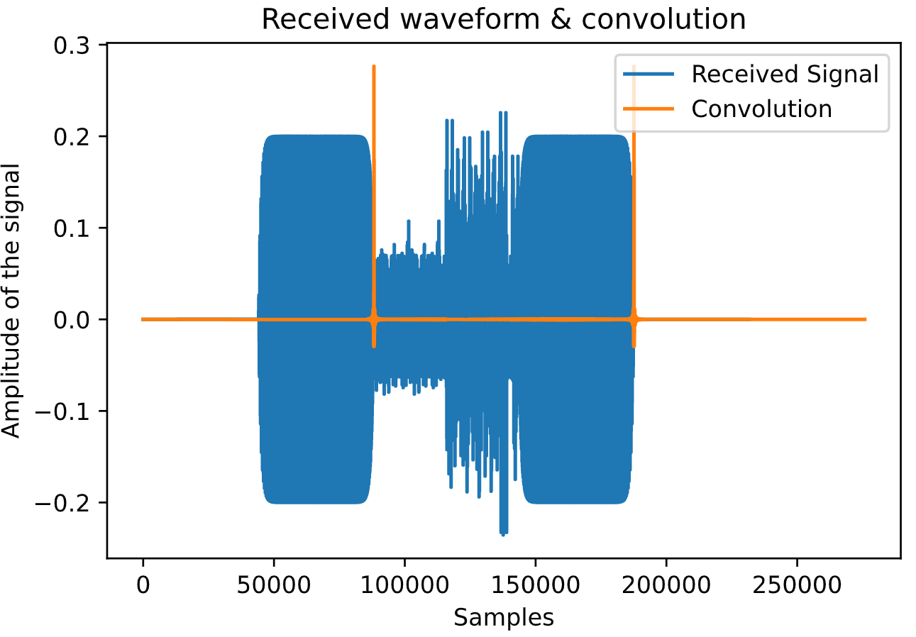
The chirp signal can be used for rough synchronisation in the system as it correlates well. There is a standard chirp which the frequency increases at the beginning and an inverse chirp where the frequency decreases with time in the end. By applying matched filtering, i.e. taking convolution with the time reversed signal, we can obtain a peak point for the rough synchronisation. The index of the peak of the convolution output therefore gives a rough estimation of the time when the chirp ends as figure below shows.
Dynamic Phase adjustment
Although chirp with fine tuning achieves a successful synchronization and produces an accurate channel estimation initially, the sampling mismatch accumulates and causes degradation in performance over time. Therefore known pilot symbols are added along with the OFDM symbols to address this issue. Cyclic time shifting property of discrete Fourier transform explains the reason why pilot symbols work: zk=x[(k−l)modN]DFT→Zn=e−j2πNnlXn
During development, we were using random pilot symbols every 16 frequency bins. Additionally, We only use the frequency range that is used by data OFDM symbols and we achieved zero bit error rate with this setup. However, the performance has dropped significantly after switching to the standard, where constant pilot symbol values of (1+j)/√2 is added every 8 frequency bins, i.e. [1,9,…,1018]. Table ??? compares the performance when using different bins for pilot symbols. It is noteworthy that when using all the pilot symbols i.e. [1,9,…,1018] specified in the standard, the performance is even worth than not using the pilot symbols for phase adjusting. This can be explained by the poor frequency response of the channel at the lower and higher end of the frequencies. When demodulating the pilot symbols, the received pilot symbol values is divided by the frequency response at that frequency. If the frequency response is lower by several magnitudes, then the response might not be accurate at the first place. Therefore, when using all the frequency bins to fit a linear regression, the gradient could be wrong and the phase adjustments for data symbols are ineffective.
The solution is to take only the pilot symbols in bins with flat frequency response to fit the linear regression and adjust the data symbols with the interpolated phase shifts. We use the frequency range of the data symbols for fitting the linear regression and achieved significant improvement compared to using all the pilot symbols as shown in the last two rows of table ???. We also compared the difference between using every 24 bins or every 16 bins and the results favour the use of every 24 bins. However, this might simply be the fact that the channel is synchronized well with little sampling mismatch and an adaptive demodulator could be designed where it could choose which pilot symbols could be used for correcting the phase shift.
LDPC
LDPC encoder and decoder is implemented in the system. The encoder part involves a metadata encoder. Repetition code is used to make sure the file header could be successfully decoded and repetition of 5 is chosen. File type and file length is encoded into 8-bit and 24-bit binary sequences respectively. Since I have not implemented the LDPC myself, I will only mention one slight modification we made on standard when we were testing the modem ourselves. The LDPC encoder requires the input bit string length to be a multiple of 24zR=972, otherwise, random padding is required. However, the standard does not enforce the random padding. We can use known padding so that when we decode the file, the known padding bits can be used as the guidance for the LLR decoder to achieve a lower bit error rate.
Comments